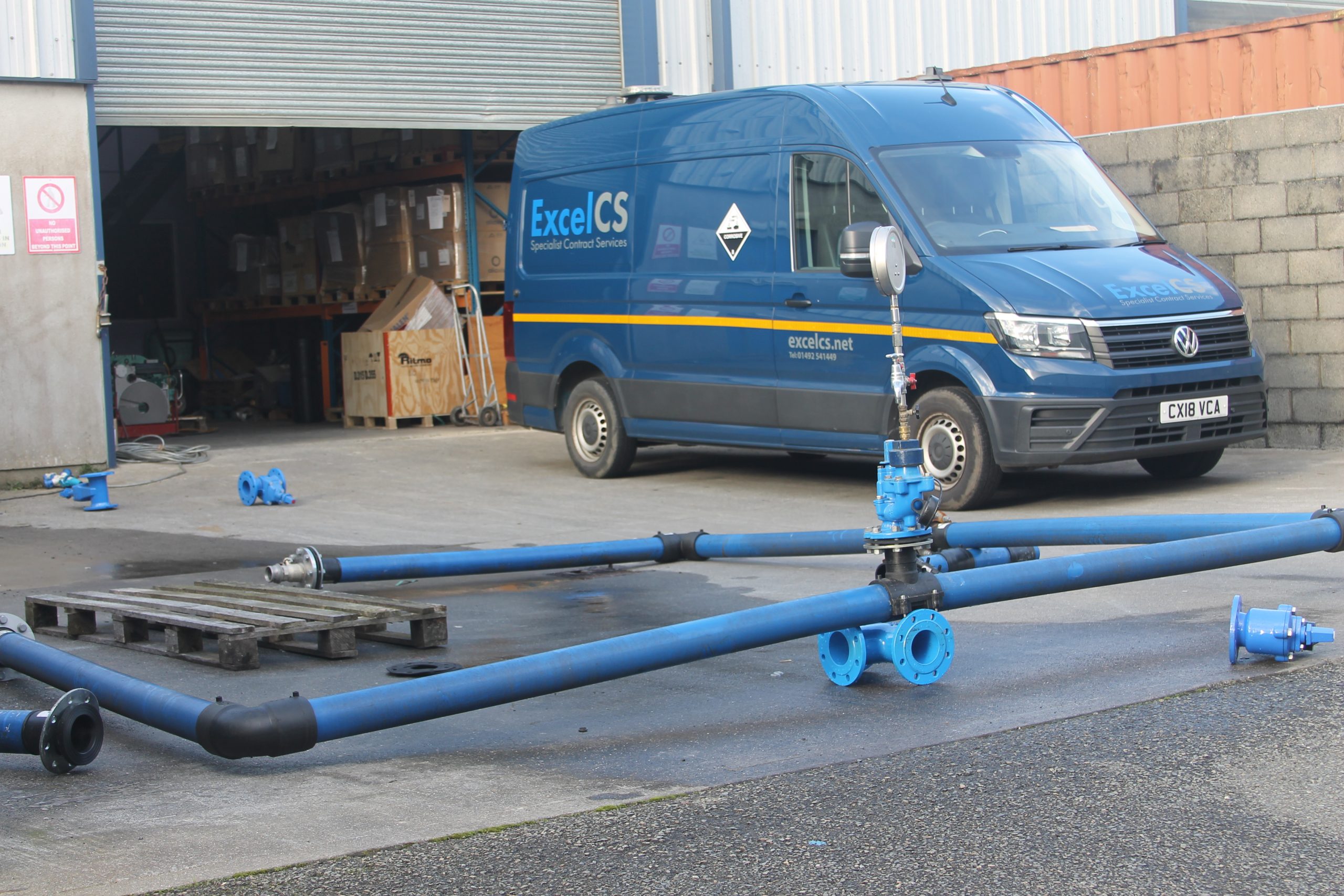
PE pipelines often connect to ductile iron valves, hydrants and flanged components at chambers, branches and network control points. Treating the interface as a coordinated assembly helps avoid missing adaptors, mismatched drilling and unsupported loads.
Identify the network function first
The fitting or valve should be selected for its role in the network and the conditions at the installation point. Confirm whether the assembly is for isolation, air management, fire-water access or a direction change.
Record the nominal diameter, pressure class and operator arrangement.
- Sluice or butterfly valves for isolation
- Underground hydrants and risers
- Air valves for release and vacuum protection
- Tees, bends and branch connections
Define the PE-to-flange interface
Confirm the PE outside diameter and SDR alongside the ductile iron DN and flange drilling. The transition may use a stub flange assembly, restrained adaptor or another project-approved arrangement.
Allow for access to bolts and for the movement needed during installation.
- PE pipe OD and SDR
- Flange standard and drilling
- Gasket, bolts and corrosion protection
- Restraint and thrust requirements
Review the complete chamber assembly
Valves and fittings should be supported so loads are not transferred unintentionally into the PE pipe. Check levels, access, operating clearances and the sequence for future removal.
Dismantling joints or risers may be required to make the assembly practical to install and maintain.
- Support and anchoring details
- Chamber level and access
- Operating spindle or hydrant position
- Removal space and dismantling provision