A polyethylene water main still needs valves, hydrants, air valves and connections to other pipe materials. These interfaces are where a straightforward pipe order can become a complicated site assembly: the PE outside diameter, valve size, flange drilling, restraint and chamber layout must all work together.
For Irish self-lay developments connecting to the public water network, the starting point is Uisce Éireann’s applicable Water Infrastructure Code of Practice and Standard Details. This guide explains the main considerations when connecting PE pipe to ductile iron valves and flanged fittings, and what to confirm before ordering.
Start with the Irish project requirements
Uisce Éireann’s August 2025 Water Code, CDS-5020-03 Revision 3, and Water Standard Details, CDS-5020-01 Revision 5, apply in full to connection applications received from 16 February 2026. Earlier applications may fall under the preceding documents. Check the connection agreement and project requirements before selecting components.
The current documents and their application dates are available on the official Uisce Éireann technical guidance page (opens in a new tab). These developer requirements should not be assumed to be the complete specification for every existing-network repair, private installation or wastewater project.
How PE pipe connects to a flanged valve
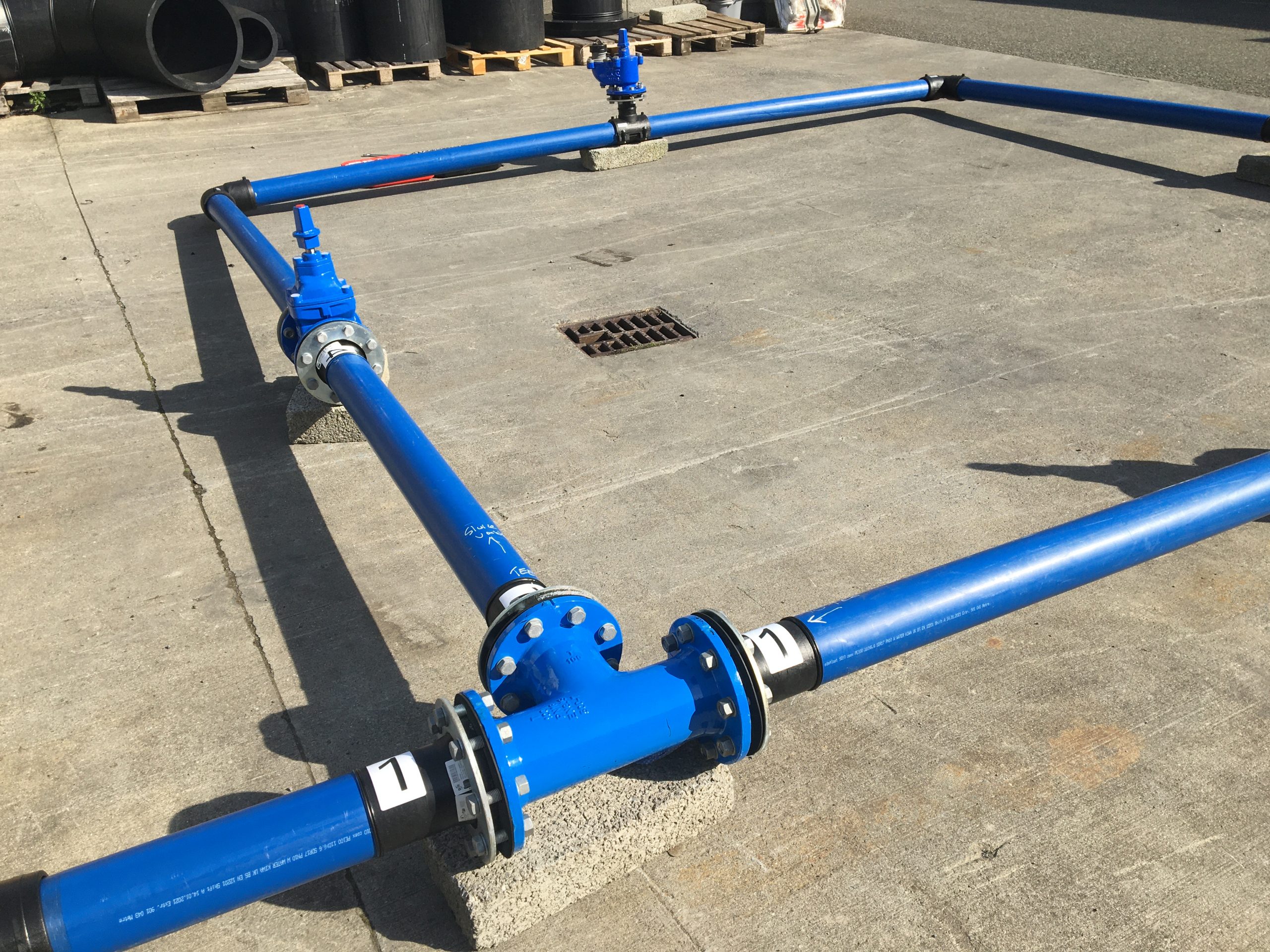
A common transition uses a PE stub flange fusion-welded to the main, with a loose backing ring providing the bolted connection to the valve or fitting. The PE component forms the transition; the backing ring distributes the bolting load. Both need to be compatible with the mating flange and the specified pressure duty.
For sluice valves in PE mains, Section 3.16 of the Water Code describes an appropriate dismantling joint and stub flange with backing ring at one end, with a stub flange and backing ring at the other. The PE stub flanges are fusion-welded into the main. The arrangement allows the valve to be disconnected for maintenance.
The Code specifically requires steel loose backing rings supplied to site to comply with both EN 1092 and ISO 9624. Do not select a ring simply because its bolt holes appear to match.
Check PE OD, valve DN and SDR separately
PE pipe is normally ordered by outside diameter and SDR, while valves and flanged fittings use a nominal size, or DN. These identifiers are not interchangeable. A PE pipe size and a valve DN should be matched through the actual transition component’s dimensions and manufacturer’s data.
Before procurement, record:
- PE pipe: material grade, outside diameter, SDR and required pressure duty.
- Valve or fitting: DN, function, pressure rating and face-to-face length.
- Flange interface: drilling standard, PN designation, backing ring dimensions and gasket arrangement.
- Installation: available space, alignment, support and the approved jointing method.
Do not infer the complete assembly’s operating or test capability from the valve’s PN marking alone. Check every component, including the PE transition and mechanical connections.
When using a mechanical flange adaptor
A mechanical flange adaptor can connect a plain-ended pipe to flanged equipment, but it must be suitable for the pipe material and the approved arrangement. A coupling that seals around a pipe does not necessarily provide resistance to axial pull-out.
Under the Water Code’s “Other Fitting Materials” provisions, flange adaptors are specified to IS EN 14525, with an allowable operating pressure of 16 bar and PN16 flanges drilled to IS EN 1092. For polyethylene, the Code requires Type 1 end restraint to IS EN 12842 and IS EN 14525. The manufacturer must supply any liners required to stiffen the pipe in accordance with its recommendations.
Liner selection is product-specific. For example, AVK’s Supa Maxi flange adaptor documentation (opens in a new tab) requires a support bush for PE pipe. Check the instructions for the exact adaptor being supplied, including pipe compatibility and insertion requirements. This example is not a statement that any particular product has project approval.
Valves, hydrants and air valves need different arrangements
The function of the fitting determines more than its size. A sluice valve provides isolation; a hydrant needs an accessible outlet and its specified supporting arrangement; an air valve requires a connection and location suited to air management.
For the sluice valves described in Section 3.16, the Water Code specifies double-flanged ductile iron resilient-seal gate valves, PN16 drilling and anti-clockwise closing. Check the specified spindle, cap and marker arrangement as well as the valve body. Do not transfer these operating requirements to every valve type without checking its section of the specification.
The Code gives separate arrangements for hydrants and air valves, including on-line and off-line installations. Use the appropriate PE Standard Detail rather than copying a ductile iron main detail and changing only the pipe label. Branch fittings, transitions and chamber positions may differ.
Restraint and support are different design checks
A restrained connection addresses axial movement. It does not automatically resolve the weight of a valve, torque from operation, ground movement or the structural design of the chamber.
Section 4.6 of the Water Code addresses anchor, thrust and support blocks. It specifically calls for concrete support blocks at hydrant tees and sluice valve fittings on PE pipelines to resist operational torque. Supports must not obstruct operation or maintenance; joints should generally remain uncovered.
The Code also distinguishes fully integrated fusion-welded PE systems from other arrangements. It does not support a blanket rule that every PE bend needs a conventional thrust block, or that PE systems never need anchorage. The designer must assess the actual configuration, changes in direction, transitions and manufacturer’s requirements.
Confirm the support and restraint design before installation. Do not use flange bolts to pull misaligned pipework into place, and do not assume the PE pipe should carry the unsupported weight of a chamber assembly.
Leave room to operate and maintain the assembly
The Water Code requires fittings such as sluice valves, hydrants and air valves to be operable without entering chambers or other confined spaces. Chamber layout is therefore part of the design, not something to resolve after the components have been delivered.
Check that the spindle can be operated from the intended position, bolts can be reached and the valve can actually be removed. Where a dismantling joint is specified, confirm its installation length and the movement available for maintenance. Avoid arrangements where a concrete support, chamber wall or adjacent fitting prevents removal.
Gaskets, bolts and coatings belong in the order
The Water Code specifies full-face EPDM gaskets for flanged joints, together with requirements for gasket material, fasteners and corrosion protection. It describes flange assemblies designed for working and test pressures of 16 bar and 24 bar respectively.
Those assembly design values are not an instruction to pressure-test every PE main to 24 bar. The pipeline test pressure and method must follow the applicable PE testing requirements and component limitations.
Order the gasket, bolts, nuts and washers as a compatible set. Follow the manufacturer’s tightening sequence and torque instructions for the actual assembly; there is no single torque value suitable for every flange size, gasket and fastener combination. Protect coating surfaces during handling and address any damage using the specified procedure.
A practical ordering checklist
Before requesting a quotation or releasing materials to site, provide:
- The approved drawing or marked-up assembly sketch.
- The applicable Uisce Éireann Code, Standard Detail and project specification.
- PE grade, outside diameter and SDR.
- Valve or fitting function, DN, pressure duty and flange drilling.
- Stub flange and backing ring details, or the specified restrained adaptor and liner.
- Gasket, fastener and corrosion-protection requirements.
- Dismantling provision, face-to-face dimensions and maintenance clearances.
- Support, anchorage and thrust-restraint details.
- Required product documentation and the agreed testing arrangements.
For fusion quality, calibration, joint records and PE pressure testing, see our guide to Uisce Éireann’s 2025 PE pipe and fusion requirements.
Coordinating the PE-to-ductile-iron connection
egeplast Ireland can help with product selection across PE pipe systems, fittings and pipeline accessories. Send the drawing and pipe specification so the discussion covers the complete interface, not just an isolated component.
Discuss Your Pipework Assembly
Sources and technical note
The principal technical source is Uisce Éireann’s Water Infrastructure Code of Practice, August 2025 Revision 3 (PDF; opens in a new tab), particularly Section 3.16 on fittings and Section 4.6 on anchor, thrust and support blocks. Obtain the applicable Standard Details from the official technical guidance page linked above.